Building Molecules
This section describes GaussView’s molecule building features. These options enable you not only to construct new structures either atom-by-atom or from fragments, but also to manipulate and examine previously-computed molecules. See the next major section of this manual, “Opening, Displaying and Saving Molecules and Views,” for information on using GaussView view features and opening and saving molecule files and images.
Placing Elements and Fragments
The GaussView molecule building tools always operate on the active View window. In general, GaussView begins and remains in its insert/replace mode, unless one of the options described below explicitly calls for it to act in a different manner. Clicking in an open area of the View window adds the current atom or fragment to the window as a distinct fragment. Clicking on an existing atom adds the current item to the existing structure at the indicated point, usually replacing it (other options are discussed later).
The desired atom or fragment is chosen using one of the , , and buttons and then selecting one of the choices from the resulting palette. The current item always appears in the Current Fragment area of the GaussView control window and/or the Active Fragment area of the standalone Builder palette (see Figure 3). Clicking on either the Active Fragment area on the standalone Builder palette or on the fragment name above the main window’s Current Fragment area opens the palette corresponding to the selected fragment type.
Note that the standalone Builder palette is opened with the View=>Builder menu item and can be made to always stay on top of all other open windows by checking the Builder Dialog Stays on Top checkbox in the Window Behavior Preferences (accessed with the File=>Preferences menu path).
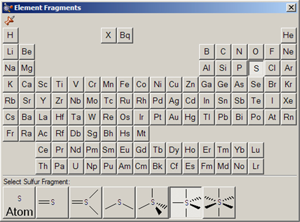
The Element Fragments palette allows you to select an element from the periodic table. The various possible coordination patterns for the selected element are shown at the bottom of the window (see Figure 11). The default element type is tetrahedral carbon.
Figure 11. The Element Fragments Palette
The available hybridization (connectivity) variations for the selected element appear along the bottom of the palette. In this case, the current atom type is pentavalent sulfur.
The R-Group Fragments window allows you to select from a series of AM1-optimized functional group fragments. It is illustrated in Figure 11. The default group is carbonyl (formaldehyde).
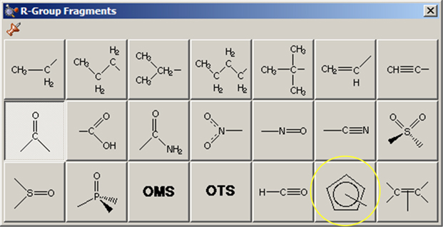
Figure 12. The R-Group Fragments Palette
Use this palette to select the desired functional group.
Note that several of the fragments use non-traditional bonding. These fragments include a five-member ring with an open bond perpendicular to the plane of the ring: a n5-cyclopentadienyl ligand for use in constructing organometallic systems (circled in Figure 12).
The Ring Fragments window allows you to select from a series of AM1-optimized ring structures. It is illustrated in Figure 13. The default ring is benzene.
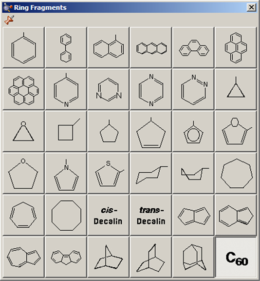
Figure 13. The Ring Fragments Palette
Use this palette to select the desired ring system.
The Biological Fragments Palette
The Biological Fragments palette presents a set of AM1-preoptimized fragments useful to biological researchers: the amino acids and various DNA bases (see Figure 13). The default biological fragment is Alanine Central Residue.
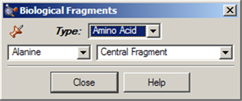
Figure 14. Selecting Biological Fragments
Use the various fields in this window to select amino acids and DNA bases.
The Type field allows you to select either Amino Acid or Nucleoside. When Amino Acid is selected, the left popup menu below the Type field can be used to select the desired amino acid, and the right popup menu in that line allows you to specify the structural form as Central Fragment, Amino-Terminal Fragment or Carboxyl-Terminal Fragment (the last two are the N-terminated and C-terminated forms, respectively).
When the Type field is set to Nucleoside, the left popup menu below the Type field can be used to select the desired DNA base (nucleic acid fragment), and the right popup menu in that line allows you to specify the structural form as Central Fragment, C3’-Terminal Fragment, C5’-Terminal Fragment or Free Nucleoside.
Making Palettes Sticky
The various palettes in GaussView can be used in a modal (dialog box behavior) or amodal (floating palette behavior) manner. The thumbtack icon in the upper left corner of the window shows whether the palette will close when another one is selected (or a non-building context is entered). The green pushed-in tack indicates that the palette is “tacked” to the desktop (i.e., “sticky”):  ; the red upward pointing tack similarly indicates modal operation:
  .
.
Placing a Fragment in a Centroid Position
The Place Fragment at Centroid of Selected Atoms item on the Builder context menu (reached by right clicking in an open area of a View window) will place the current element, R-group, ring or biological fragment at the centroid position defined by the currently selected atoms. For example, to place an atom inside a C60 cage, select all of the atoms in the molecule, select the desired atom from the Element Fragments palette (specifying the bare atom type), right click in an open area of the view, and select Builder=>Place Fragment at Centroid of Selected Atoms. This process is illustrated in Figure 15.
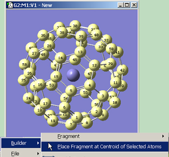
Figure 15. Placing a Centroid Atom in C60
Note that if you simply want to define the centroid location without immediately placing any atoms there, you can use the dummy atom (element type X) to do so.
Atom selection methods are discussed in detail in a later section below.
Undo and Redo
The Edit=>Undo and Edit=>Redo menu paths may be used to reverse or reinstate a previous molecule modification or other action. The button and the button may be used for the same purposes.
Viewing and Adjusting Structure Parameters
The Builder toolbar/window includes the following buttons for viewing and modifying the structural parameters of molecules: , , , , , , and . In addition, other buttons and their corresponding menu items also affect molecular structure—including , , and —and display. We will consider these features in this section.
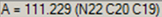
The button allows you to request geometric information directly from the View window when you click on the atoms of interest. Note that the selected atoms do not need to be bonded. The structural information appears in the View window’s status bar, as in Figure 14. The number of atoms that you select affects the resulting display on the View window:
 .
. .
. .
. .
. .
.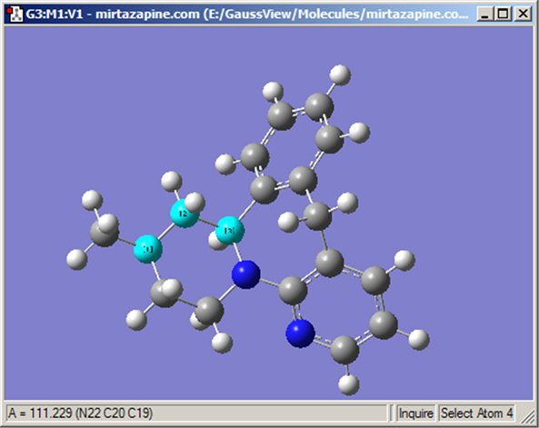
Figure 16. Inquire Mode Display
This display shows the value of the selected bond angle in the window’s lower left corner.
Three buttons, the button, the button, and the button, allow rapid and intuitive modification of geometric components. Once selected, the atoms of the bond in question must be selected for the respective SmartSlide dialog box to open. Once you have modified a parameter using the SmartSlide, the OK button must be pressed before any of the changes made on any SmartSlide are actually applied to the molecule. Clicking the close box will discard any changes (as will selecting the Cancel button).
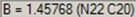
The Bond SmartSlide is illustrated in Figure 17. The initial bond length value is set to the distance between the selected pair of atoms, and the type of bond existing between them is indicated. The SmartSlide provides access to all the possible bond types.
The interatomic distance is dynamically adjusted by moving the slider along the scale. Values may also be directly entered in the text box.
You can change the bond type by clicking one of the bond type radio buttons without affecting the valence on the atoms from which the bonds are removed.
Note that the Bond SmartSlide is also used to add bonds between unbonded atoms. Simply click on the two atoms to be bonded as usual. When the SmartSlide opens, click on the type of bond desired, and the bond will be created. Similarly, to remove a bond, select the two atoms you want to unbond, and then select the None radio button in the dialog.
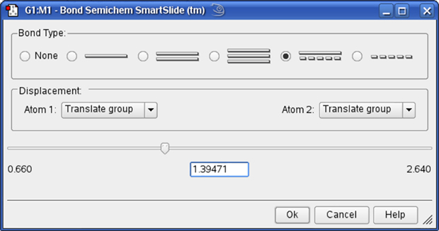
Figure 17. The Bond SmartSlide
This dialog can be used to add, remove and change bond lengths.
The Displacement fields specify how attached groups are handled as the bond distance changes:
Figure 18 illustrates the effects of different combinations of these choices.
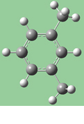 Original |
 1=Fixed, 2=Translate Atom |
 1=Fixed, 2=Translate Group |
 1,2=Translate Group |
Figure 18. Bond Length Modification Options
All three of these structures result from lengthening the bond distance between the two selected C atoms (to the same value in all three cases). In the left picture, atom 1 was held fixed, and atom 2 was set to Translate Atom. Compare this to the middle picture which also held atom 1 fixed and set atom 2 to Translate Group. The upper methyl group stays fixed in the first case, while the 1-2-R bond angle remains unchanged in the center case. The right picture sets both atoms to Translate Group, probably the most common choice for a case like this one.
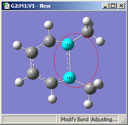
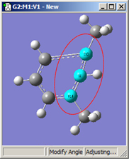
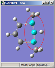
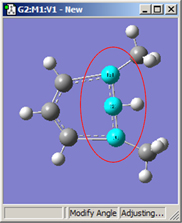
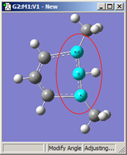
The Angle and Dihedral SmartSlides
Figure 19 illustrates the dialog associated with the Angle SmartSlide. The dialog for the Dihedral SmartSlide is similar, but it includes Displacement fields only for Atom 1 and Atom 4.
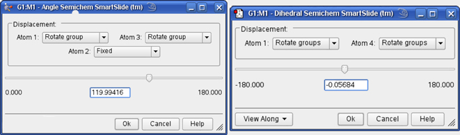
Figure 19. Angle and Dihedral SmartSlides
These dialogs modify bond angles and dihedral angles.
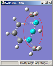
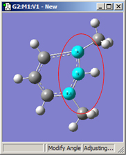
Figure 20 illustrates some of the combinations of various Displacement settings for bond angles (using the same original molecule as Figure 18). The possible choices are:
The View Along popup menu in the lower left corner of the Dihedral SmartSlide dialog allows you to reposition the molecule using a Newman projection, along the 2,3 internuclear axis or the 3,2 internuclear axis.
 1,2=Fixed, 3=Rotate Atom |
 1,2=Fixed, 3=Rotate Group |
 1,2=Fixed, 3=Translate Group |
 1,3=Rotate Atom, 2=Fixed |
 1,3=Rotate Group, 2=Fixed |
 1,3=Translate Group, 2=Fixed |
Figure 20. Bond Angle Modification Options
All six of these structures result from increasing the 1-2-3 bond angle. In the top row, atoms 1 and 2 are both held fixed. Compare the results of increasing the bond angle to the same value in the three cases (keeping in mind the “normal” position for the ring atoms and the methyl groups). The movement of the methyl group attached to atom 3 ranges from substantial in the first frame to a little in frame 2 to almost none in frame 3. In the second row, atom 2 is held fixed while other choices are used for atoms 1 and 3. Comparison of these illustrations as well as experimentation will make the differences between the choices clear and familiar.
The button attaches additional valences (shown as hydrogen atoms) to the center clicked with the mouse. The new valences will be placed as far as possible from the other atoms attached to the center.
Similarly, the button removes atoms and open valences. When used, the function will eliminate the selected atom and all single valences (hydrogens) attached to it. It may also be used to remove a dangling bond by clicking on the bond stick (see Figure 21).
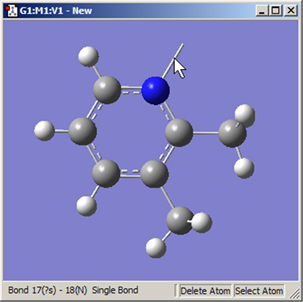
Figure 21. Deleting a Dangling Bond (Open Valence)
The Delete Atom button may be used to remove atoms and dangling bonds. An example of the latter is shown at the top of the molecule. Clicking on it will remove the open valence.
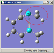
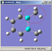
Invert About Atom (Mirror Invert)
The button allows you to reverse the symmetry of a molecule with respect to a selected atom. Figure 22 illustrates the use of this feature.
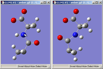
Figure 22. Inverting a Structure About an Atom
Clicking on the nitrogen atom with the Invert About Atom tool will result in the structure on the right.
The button and Edit=>Clean menu items both adjust the geometry of the molecule, based on a defined set of rules, to more closely match chemical intuition. The results are only approximations and are not intended to be perfect. Geometries may require adjustment for non-classical cases such as transition states.
The GaussView clean function may be customized via the Clean Controls Preferences panel (illustrated in Figure 23).
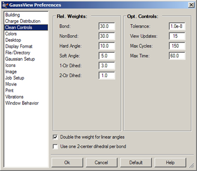
Figure 23. Customizing the Clean Function
You can use this preference panel to modify and customize how the GaussView clean function operates.
The default clean settings attempt to achieve a balance that produces expected “normal” results. Altering the settings in Clean Controls Preferences can cause unexpected and undesirable results, so please read the following sections carefully before making any changes.
The following controls are available in the dialog. The fields in the Rel. Weights column are:
The checkboxes at the bottom of the window have the following effects:
The fields in the Opt. Controls column are:
It is important to remember that the various components of the clean force field are relative. Changing one weight will affect the behavior of the other weights. For example, an excessive non-bond weight will produce longer bonds. Similarly, an excessive hard angle weight could affect the 2-center dihedrals.
You can disable any set of terms by assigning a weight of 0.0. For example, disabling the 1-center dihedral term can result in faster cleaning, but the resulting tertiary structure may not be as nice. Do not disable the bond weight or hard angle terms. The former should be kept high relative to the other terms.
Clean Performance Tips
If the clean function is too slow on your system, try these settings:
Poor performance of the clean function can also be a symptom of a memory shortage on the system.
The button and Edit=>Rebond menu path both initiate a rebonding process in which GaussView reidentifies bonded atoms, based on a distance algorithm. Note that Gaussian usually does not use the bond information on the screen for calculations. This information is presented primarily to make it convenient for you to visualize the chemistry of the molecule.
The Point Group Symmetry dialog is used to specify the desired symmetry for a molecular structure (see Figure 24). It is reached via the Edit=>Point Group menu path. The controls have the following meanings:
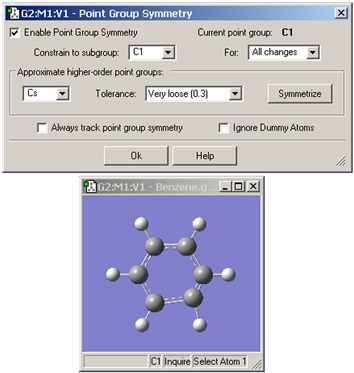
Figure 24. Imposing Symmetry on a Molecular Structure
In this example, GaussView has identified the current point group of this distorted benzene molecule as C1. It also recognizes that the C2v point group might also be appropriate. Clicking the Symmetrize button will apply the specified point group to the structure. The Tolerance field can be used to tighten or relax the symmetry identification process. In this case, loosening the tolerance allows GaussView to identify the highest applicable point group as D6h.
The button (on the toolbar) and the Edit=>Symmetrize menu item both immediately impose the maximum identifiable point group on the current structure, using the most recent Tolerance setting from the Point Group Symmetry dialog for this molecule (or the default of Normal). They also have the side effect of enabling point group symmetry for the molecule (again, using the previous settings, if any).
The View window status bar will indicate any identified and constrained symmetry for the molecule, as illustrated in Figure 23.
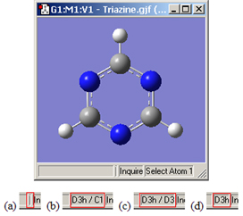
Figure 25. Symmetry-Related Status Bar Displays
Four views of the symmetry information section of the status bar for the triazine molecule: (a) symmetry has not been turned on; (b) molecule symmetry (D3h) but no symmetry constraint (C1); (c) molecule symmetry (D3h) and structure constrained to D3 symmetry; and (d) molecule symmetry and constraint symmetry are both D3h.