Periodic Boundary Conditions (PBC)
Tutorial 2 - Build a Graphite Sheet From Benzene, PBC/2D
2-1 Create a new molecule and corresponding view window by clicking on the New toolbar button and selecting Create Molecule Group.
2-2 Make the benzene fragment the "current fragment" by double-clicking on the Ring Fragment tool button and then clicking on the "benzene" button in the Ring Fragment palette.
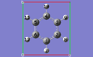
2-3 Click anywhere in the empty view window to create a benzene molecule.
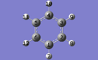
2-4 Center the molecule in the view window by clicking on the Center toolbar button.
2-5 Turn on atom labels for the view window by checking Labels from the View menu of the main window.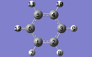
2-8 Show the PBC dialog for the molecule by selecting PBC from the Edit menu of the main window.
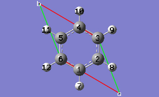
2-9 In the Symmetry tab of the PBC dialog, select Two from the Lattice Dimensions drop-down list.
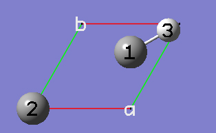
2-10 In the Cell tab of the PBC dialog, push down the Place button and make sure Vertex is selected to enable placement of the cell origin (O (0,0)) vertex at any atom selected in the view window using the mouse. In the view window, click on atom 6.
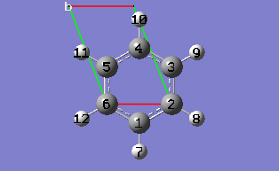
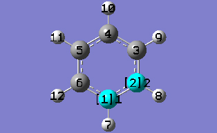
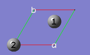
2-13 In the Cell tab of the PBC dialog, select Delete All Atoms Outside Cell from the Trim Contents drop-down list.
2-14 Delete the hydrogen atom by clicking on the Delete Atom toolbar button and then clicking on the hydrogen atom in the view window.
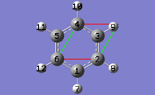
2-15 In the Cell tab of the PBC dialog, click on the Center Contents button.
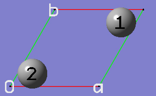
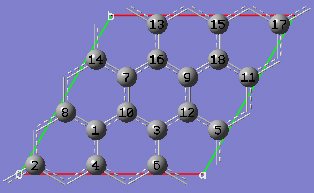
2-16 At this point we have defined a primitive unit cell for a PBC/2D model of graphite.
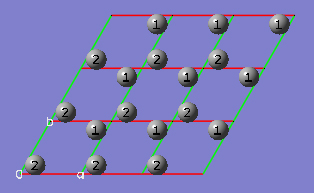
2-15 In the View tab of the PBC dialog, show three cells along both the "a" and "b" axes by selecting 3 from the corresponding spin boxes in the Cell Replication section. By default, the contents of replicate unit cells are shown in Low Layer format.
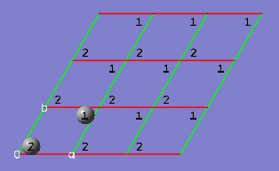
2-16 In the View tab of the PBC dialog, select Normal from the Replicate Contents Display drop-down list to show the replicate contents in the same format as the reference unit cell contents.
2-17 In the Contents tab of the PBC dialog, select the Rebond All item from Bonds popup menu to update the bonding between all atoms.
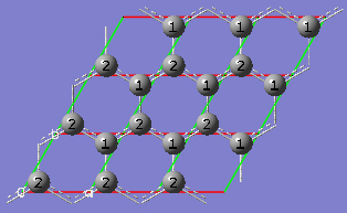
2-18 In the View tab of the PBC dialog, click on the Combine button in the Cell Replication section. This will cause the reference unit cell and the replicate unit cells shown on screen to be combined into a larger "supercell" which is nine times the primitive unit cell. Note the atom number changes. Note also that the number of cells being viewed is automatically reduced to one to avoid potential confusion.